Saturday, April 28, 2012

One more in the 'Done' column

I was supposed to go to Lime Rock Park today to watch the Porsche Owners Club flog their cars around the track.  While I'm usually up for anything to do around a racetrack when I walked out to the bike this morning at 8am and saw a frozen puddle in the street the 2 hr ride to the track suddenly seemed much less attractive.  I made the obligatory 'I gotta back out last minute' call, took the heat, then went back to bed!

After a couple hours more nice warm sleep I decided to make some use of the day and finish up the swingarm pivot plates.  The shop was deserted and quiet, nice conditions to make some progress.

I had left the parts setup in the mill so that realignment for the bearing bore operations would be easy.  I can use the same boring bars used for the engine bearings.  The bores went quickly, so fast I missed them with the camera!  Strike that, I had dropped them in the wrong folder.

Bore out one bearing hole...
Then flip it and bore the other:
Machining the reinforcing rib tapers and surfacing the outside of the bearing tunnel:


With all the fixtures and programs done and verified, making a second part only took a couple of hours:

The parts look great and I'm one step closer to getting Scott down for some sheet forming and welding sessions.

Next up is the upper shock mount crossbar, a much simpler part that should go quickly.

Free t-shirt to first person that spots something that's amiss in the pictures.  Post it in the comments and google will be the time-stamp arbiter.


UPDATE:  here's the problem that can be seen with a close examination of the second to last picture:

That slot in the bearing pocket shouldn't be there!  It was a problem with a Z retract value that was defined incrementally instead of absolutely so when the tool went to start the finish pass the Z retract did not retract enough and instead of clearing the part plowed through it.

I'll have Scott Kolb weld this mistake up and then remachine the bore to size.  Normally there would be a concern about the welded material in a stressed area losing its temper and strength but this part will be heat treated after the entire swingarm is welded so it will then regain its full T6 temper strength.


Chris

Friday, April 27, 2012

Progress on the Swingarm Pivot Plate

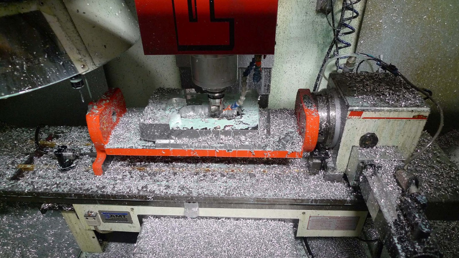
Over the past few days I was able to get more machine time in on the swingarm pivot plate.  I made a lot of progress but didn't quite finish up.   For the first time in a while I had a couple of broken end mills slow progress down.  The order of some roughing operations was incorrect and when you have a 1/2 end mill sticking out of the collet 2 1/2" it doesn't take much of an unmachined area to increase the chip load make the end mill snap like a twig.
The fracture surface is something I find interesting.  These cutters are made from cemented tungsten carbide, an extremely hard material made by sintering extremely fine metal powders under high temp and pressure.  The resulting material will quickly dull a common shop file and still retain an unblemished mirror finish.  The only drawback, and is shared by many ultra high strength materials, is that it is brittle.  You can load it agressively but not quickly.  Unplanned high loads, say like plowing into an unmachined area, make the material behave more like glass than metal.  You can see the fracture surface is extremely smooth and none of the tearing appears that is exhibited by most lower strength materials.

This clean fracture is an indication of high quality material.  There is no bending or elongation with carbide.  It's all or nothing, and in this case, nothing.  The good thing about mill tool breakages is that if you catch it before a toolchange then usually it's nothing more than resetting the milling chuck with a new end mill.  that's what happened this time, no part damage, just a slight snap and then silence.

To rewind a bit to where we were at in the previous post, I had the part blank in its usual place on a subplate on the trunnion:
I then used that wonderful Ripper insert mill that was used on the TZ cases to do some serious roughing and break through to the shock pocket machined in the previous operation.
This left the part in a semi-recognizable state.
Then used a 1/2 ball end mill to surface machine the outside of the pivot bearing tunnel:
Then index the table 90 degrees and rough machined the bearing bores and finish machined some of the interlocking features that locate the aluminum sheet parts:
Which left the part in this state where I called it quits for the day:
The next step will be to break out the boring bars and machine the dual bearing bores on this side.  Then I'll spin the table again and machine the opposing side and the bearing bore for the dual needle bearings.

The pivot bearing arrangement is one that I thought was designed quite cleverly, then upon further research seemed to be the way most modern Japanese sportbikes are done!  One major design constraint of the swingarm pivot is to keep the bearing diameter as small as possible in order to keep the sprocket to pivot distance as small as possible.  This is desirable because it both reduces the variation in chain tension and allows for a longer swingarm for a given wheelbase, a rare win-win situation.
This pivot axis uses a dual needle roller bearing on the chain side because needle bearings are very low profile and can handle high radial loads.  This allows me to keep the pivot close to the sprocket and withstand the considerable chain pull forces.  However needle roller bearings no not provide any axial load capacity so something else needs to be done to keep the swingarm from flopping from side to side when the bike leans.  On the side opposite to the sprocket there is some more room for a larger diameter bearing so that's what I do.  The double row ball bearing provides excellent axial load capacity when installed with a retaining ring and just to be safe on the radial load rating I tuck another needle roller bearing in next to it.  There is a long hardened steel inner race that the needle bearings ride on and this inner race is clamped against the inner race of the ball bearing in order to provide a continuous inner stackup that can be torqued down against.  This arrangment leads to a very rigid pivot joint, a desirable trait in any axis of motion.  Of course, both sides are sealed in with low friction shaft seals.  A dirty bearing is a horrible sight on a racebike.

Hopefully these features will be machined this weekend.

Chris

Wednesday, April 25, 2012

Thanks Guys

Here's a little update on the fundraising front.  T-shirts have been going out to the twenty or so people who generously contributed at that level.

I've also had one taker of the $250 level for fairing display and that was Chris Hodgson from San Jose BMW.  I've known of Chris since his days with CC products, having been exposed to the rare BMW motorcycle racing bug through Gregor's Boxer project.  The engine was stuffed full of CC goodies.  I also met Chris a couple of years ago when he pitted next to Scott's LSR bike at Bonneville.  I had some of the V4 engine parts with me to show at the AHRMA Miller round and he was like 'Hey, I follow that project online!'.  It was a rare moment of the student becoming the master, or something like that.  Anyway, Chris dug deep and helped out.  Thanks!

Over the weekend I had the first $500 donor to have his logo engraved on the engine cases.  The person was Lawrence Smith, an Aussie that not only loves performance bikes, and not only knows machining and engineering, but is a FFE (funny front end, an industry term...) advocate!  Amazing!  How do you know he is a FFE lover you ask?  Well, this is his first project bike:
Pretty damn cool looking IMO.  There's a nice writeup with some pics and video over at TheKneeSlider.  Lawrence is very happy with how the bike performs and in his own words 'after all FFE is the future'

He sent me some pictures of his next project that just got on the road:

Lawrence took nearly the opposite approach to me in his effort:  he wanted to maximize reuse of an existing bike and do something that would get him riding quickly.  His use of the girder with its steered arms is one of the decisions that made a retrofit easier as he could still use a headstock style frame, although heavily modified in that area.  His results are impressive and allow easy back to back comparisons with stock bikes.  I'm sure that has he gets the geometry optimized it will be a very positive comparison for the FFE.


Anyway, that was really cool of him to contribute to my project when he has his own going on too.  You rock.

Some more swingarm pivot plate machining will be coming soon.

Chris